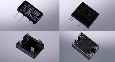
Solid State Relays
The non-contact control component of the semiconductor using a semiconductor element to the electric circuit opening and closing portion.
Precautions for use
1. Precautions for Input Side
(1) SSR Input Voltage
Pay attention to rising and dropping speed and chattering of the input voltage for driving a SSR. Besides, apply a voltage within the input voltage range indicated in the characteristics item of each type.
(2) Input Opening and Closing Speed of the Input
To avoid cause of malfunction or become less able of the ON/OFF, set the opening and closing speed as follows,
| DC Load Opening and Closing | AC Load Opening and Closing |
|---|---|
| 100Hz or lower | 10Hz or lower |
(3) When Input Voltage Fluctuates
When the input voltage fluctuates, adjust the voltage so that the input voltage reliably remains within the range of the upper and lower limits of the input voltage when ON, and remains at low level below the release voltage of the voltage detector (VD) when OFF.
(4) When Input Voltage includes a Ripple in DC Input SSRs
In the case of a rectification power supply where the input voltage includes a ripple, set the voltage so that the valley voltage of the ripple becomes beyond the lower limit voltage of the input voltage range, and the peak voltage becomes below the upper limit voltage.

(5) When the Input Voltage Exceeds Maximum Input Voltage Rating in DC Input SSRs
When the input voltage exceeds the maximum input voltage, insert external series resistance to prevent a voltage beyond the maximum input voltage rating from being applied.
(6) Measure against Noise
When noise occurs on the input side, a malfunction may occur. As a measure, shorten the routing of the input line, or isolate the input line away from high voltage lines or large current lines.
- 1) Inductive Noise
When a cable is used for the input line, it is effective to use a twisted pair wire or shielded wire as measures against electromagnetic induction and electrostatic induction. - 2) Pulse Noise
Since a malfunction may occur by a quickly rising noise voltage, it is effective to provide an external noise absorbing circuit, such as by a capacitor (C) or resistor (R).
(7) Reverse Connection to Input Terminal (DC Input Type)
The polarity is indicated on the SSR. If the polarity is connected mistakenly, as well as not operating, but also the SSR may be damaged. Pay sufficient attention to the polarity when connecting the signal lines to the input terminals.
(8) Misconnection of Input and Output
Pay sufficient attention, as the SSR will be damaged if the input and output are connected mistakenly.
(9) Input Current
The resistance (impedance) of the input circuit differs by the type of SSR. Pay attention to the current capacity on the drive side. There is also a type that is controlled by the current, so pay attention to the input side specification.
2.Precautions for Output Side
(1) Overvoltage
- 1) When an overvoltage beyond the peak repetitive off-state voltage (VDRM) is applied to the output side, it will not only cause malfunction, but also may damage the internal components of the SSR. Also pay attention to momentary overvoltage.
- 2) Do not apply a continuous voltage exceeding the load voltage range.
- 3) When there is a possible application of momentary overvoltage by a noise and surges which overlap between the lines (back electromotive force from a contact switching surge, voltage fluctuation, inductive load, etc.), it is recommended that preventive measures be taken for surge generating sources, and connect surge absorbing components including a varistor between the output terminals of the SSR. (This is not applicable for types with a built-in varistor.)
【Reference】

- (4) When a voltage current exceeding the varistor rating is applied when connecting a SSR with a built-in varistor or a varistor, the varistor may also be damaged.
- (5) As a measure against overvoltage which rises suddenly, consider connecting a high-speed operating overvoltage suppressing component.
- (6) When there is an excessive critical rate of rise of the OFF-state voltage dV/dt (overlapping noise in the power supply, etc.), or a critical rate of rise of the OFF-state at the commutation voltage (dV/dt) c (occurs when the SSR is OFF if there is a voltage current phase difference between the SSR output terminals), a malfunction or stoppage trouble may occur. Therefore, carefully confirm the operating conditions.
As measures, there is a method to adjust the snubber constant, or change to a SSR with a larger current capacity.
(2) Overcurrent
- 1) When a current exceeding the surge current rating (refer to the characteristics graph by type) occurs due to a load short circuit or other reason flows in the output side, the internal components of the SSR may be damaged. It is recommended that a fast-acting fuse or breaker be used to protect the internal components. (The surge current rating of the SSR indicates the component resistance to sudden surge currents, and is not applicable to repetitive surge current.)
[Selection of Fast-acting Fuse]- - Select a fast-acting fuse that consists of the pre-arcing time current characteristic IFF in series on the output side, which melts at 1 peak cycle of the surge current rating (ISURGE) of the SSR or less, or the load inrush current (IR) or more.
Protection coordination conditions: ISURGE > IFF > IR -
- There is another method of selecting a fuse by comparing the current squared time (I2t).
SSR (I2t) > Fuse (I2t)
SSR (I2t) = ∫0th(ISURGE/√2)2dt
ISURGE: 1 peak cycle of surge current of SSR
th: Half cycle time of operating frequency - - Fuse (I2t) = Refer to the specified value of the fuse manufacturer.
When using a SSR with an ISURGE of 225A on a 50Hz sine wave
(225/√2)2×0.01 ≠ 253(A2SEC)
Select a fuse where the (I2t) is smaller than 253 (A2SEC).
* The above shows a typical selection method. It is recommended that sufficient verification with an actual load be performed based on the formula before use.
- - Select a fast-acting fuse that consists of the pre-arcing time current characteristic IFF in series on the output side, which melts at 1 peak cycle of the surge current rating (ISURGE) of the SSR or less, or the load inrush current (IR) or more.
- 2) Depending on the load, an inrush current 10 to 40 times of the load rating or more may flow during the initial operation. When selecting a SSR, confirm the inrush current and duration of the load, and select a product with sufficient margin.
If there is a possibility of the inrush current exceeding the surge current rating of the SSR, there is a method to insert a protective series resistor RS, or a protective series inductance LS to the load in-series as a measure.
Protective series resistor RS > √2 x load voltage / 1 cycle surge current rating
Wattage of protective series resistance RS > (load current)2 x series resistance value RS
Protective series inductance LS = 100 to 500µH* The above shows a typical selection method. It is recommended that sufficient verification with an actual load be performed based on the formula before use.
(3) Leakage Current
- 1) Even when an input voltage is not applied, a leakage current flows to the output side of the SSR through CR snubber circuit. For the precautions on operation, refer to precautions in 3. (4) Low Current Loads.
- 2) According to the phenomenon in 1), when routing wires or replacing a SSR, be sure to turn OFF the power supply on both the input/output sides, and confirm the safety to prevent electric shock.
(4) Low AC Voltage Loads
When the electric load is used below the minimum value of the load voltage range of the SSR, the lost time of the voltage applied to load becomes longer. Please confirm before use that this lost time does not become a problem in actual use. If the load voltage becomes below the load voltage range, the SSR may not turn ON. Set the load voltage to within the load voltage range.
(5) Ambient Temperature
The current which flows through the SSR changes with the ambient temperature. Be sure to use the SSR within the range of the load current characteristics curve for each product.
3. Precautions for Types of Loads
(1) Resistive Loads
- 1) An excessive inrush current flows through lamp loads. Check the current value and duration to prevent the rating of the SSR from being exceeded. (Particularly, a large current flows through a mercury lamp for several minutes.)
- 2) There are certain heating loads in which the resistance changes with temperature. Keep the current which flows into the SSR from exceeding the rating.
(2) Inductive Loads
- 1) The counter electromotive force of parts with high inductive loads, such as motors, magnet relays, solenoids, and solenoid valves, etc., become overvoltage when the load is OFF, and causes malfunctions and damage of components.
It is effective to use an overvoltage suppressing component, such as a diode or varistor in combination. However, when using a varistor, use it in the following conditions.
VOMAX > EO+EZ VOMAX: Maximum load voltage of SSR EO: Power supply voltage EZ: Varistor voltage - 2) Since inductive loads may produce an excessive inrush current, consider the current and select a type with a margin.
- 3) When selecting a SSR with a zero crossing function for loads with a large voltage current phase difference, malfunction of the SSR may occur when a critical rate of rise of the OFF-state at the commutation voltage (dV/dt) c exceeds 40V/200µsec. Therefore, it is recommended that a SSR without the zero crossing function be selected.
(3) Capacitive Loads
- 1) Load types such as coupling capacitor switching power supplies and motors with a capacitor connected, when the SSR is OFF, the condenser charge voltage could become overvoltage because of the power supply superimpose and charge-discharge charging is overcurrent.
Take sufficient measures against overvoltage and overcurrent on the output side.
As a measure against overvoltage, it is effective to connect a varistor, and insert a protective series resistor RS for overcurrent. - 2) Select a SSR with a load voltage range of 2 times or more of the power supply voltage, and a withstand surge current 2 times or more the charging and discharge current.
(4) Low Current Loads
- 1) Use a SSR beyond the minimum load current for each type. If a SSR is not used beyond the minimum load current, it may not turn ON or OFF, or cause malfunctions.
- 2) When using a load below the minimum load current, connect bleeder resistor (shunt resistor) RP in parallel to the load which enables the minimum load current or more to flow.
- 3) The ON state of a low current load and high sensitive load is maintained due to leakage current when the SSR is turned OFF, and may not turn OFF even after the input voltage is cut off. In such a case, connect a bleeder resistor (shunt resistor) RP in parallel with the load to reduce the leakage current flowing to the load when the SSR is OFF, and adjust to a level where the load operating state is not maintained.

RP: Shunt Resistor IR: Load recovery current ILEK: Leakage current when SSR is OFF (actual measurement value) RL: Load impedance E: AC power voltage ・ The shunt resistor RP value is derived through the following formula.
A simple guide is a similar value to the load resistor RL.Parallel Shunt Resistor RP < IR×RL / ILEK-IR
・The parallel shunt resistor RP wattage P is derived through the following formula. However, please leave a buffer by selecting models of at least twice the calculated value.
Parallel Shunt Resistor RP Wattage P < E2 / RP
(5) Specific Loads and Operating Conditions
- 1) The SSR may not operate stably under specific load conditions and power supply environments which do not conform to the SSR.
Carefully confirm the operating conditions in advance before use. Particularly, the SSR may not operate stably with a load where the load current is below the minimum operating current of the SSR, a load where the operating current waveform is not a sine wave, or a load with self-oscillation, etc. Therefore, carefully confirm the operating conditions and observe the voltage current waveform. - 2) SSRs cannot be used in-series to increase the withstand voltage, or used in parallel to increase the current capacity. Be sure to use a single SSR that satisfies the rating for these applications.
- 3) When the load is a solenoid valve including a full wave rectifier, recovery trouble may occur.
- 4) Do not use a SSR for electric loads of a waveform controlled by an inverter or a pulse waveform. A malfunction of the SSR will occur, or make recovery impossible.
4. Precautions for Designing Heat Dissipation
A semiconductor for the load switching component of a SSR therefore, when the temperature on the connected portion of the components exceeds the allowable value, malfunctions, damage of the SSR, or deterioration of the components will occur, which remarkably deteriorates the reliability.
Designing heat dissipation becomes an important point when using a SSR.
(1) Heat Sinks
Regarding the types which require a heat sink, use the standard heat sink of our company indicated in the load current characteristic curve together with silicone grease. Also, completely remove burrs or irregularities on the heat dissipation contact surface to prevent the adhesion of dust, so that the heat dissipation ability is not obstructed.
When using a heat sink other than the standard heat sink of our company, carefully consider the heat dissipation conditions.
(2) Safety
- 1) During operation, SSRs reaches to high temperatures. Avoid not to touch the body of SSRs or heat sink.
- 2) Be sure to securely ground the heat sink (aluminum base portion) of the SSR body for heat sink mounted type SSRs.
(3) Designing Heat Dissipation
- 1) Use the SSR in under conditions avoiding fluctuations of the power supply voltage and increases in the ambient temperature and additional heat dissipation.
- When SSR is used in an enclosed environment or multiple use in close proximity, please consider the heat dissipation with an greater margin of the air flow conditions and the heat interference between the SSRs.
- 2) In order to acquire even better heat dissipation characteristics, mount the heat sink in a direction where the air flow across in the most effective way.
5. Handling and Other Precautions
(1) Soldering
- 1) When mounting SSRs on boards, it is necessary to pay attention because contamination by the flux will affect the reliability of SSRs. Use a non-corrosive rosin flux and alcohol based diluent with low chemical reaction.
- 2) Note that the heat stress of soldering will affect the reliability of SSRs. Perform the soldering of the terminals of the solder terminal type SSRs at a temperature of 250 ºC in 10 seconds or less.
- 3) Contact our company if you are considering the use of Faston terminal type SSRs by soldering.
(2) Terminal Forming
Do not apply stress to the SSR when forming the lead terminals of printed circuit board mounting type SSRs.
(3) Tightening Torque
- 1) The allowable tightening torque of the terminals of a screw terminal type SSR is as follows.
M5 screws: 2.0 N-m max (Recommended value: 1.73 to 1.94 N-m)
M4 screws: 1.5 N-m max (Recommended value: 1.22 to 1.43 N-m)
M3 screws: 0.8 N-m max (Recommended value: 0.66 to 0.76 N-m)
Connect the SSR to electrode terminals appropriately and securely. If a current flows while the connection is incomplete, it will cause abnormal heat generation or fire. - 2) Securely attach the SSR body and heat sink. If not, it will cause insufficient heat dissipation.
- 3) The allowable tightening torque of the mounting screws between the SSR and heat sink is as follows.
M4 screws: 1.5 N-m max (Recommended value: 1.22 to 1.43 N-m)
M3 screws: 0.8 N-m max (Recommended value: 0.66 to 0.76 N-m)
(4) Cleaning
- 1) When cleaning a SSR, there are types of detergents that may damage the external resin and case or erase the marking of SSRs.
- 2) Avoid using ultrasonic cleaning as it may affect the internal semiconductor device.
(5) Impact, Vibration and Applying Weight
- (1) Avoid SSRs from strong impact and dropping. If it happens, please confirm the characteristics and performance of the appropriate SSR before usage.
- 2) Avoid to put on heavy objects on the SSR. It will cause failure as bending and deformation of the terminals, etc.
- 3) Due to the structure of the system, do not apply excessive impact or vibration even to the connecting portion or soldering portion of the SSR. It will cause wire breakage or malfunction.
(6) Storage and Operating Environment
- 1) Keep dripping water,solvents and steam away from the SSR which will affect the resin. Do not store or use SSRs where there is condensation.
- 2) Do not use a SSR in environments (dispersion of solvent vapors, dust and oils, etc.) which will affect the resin.
- 3) Do not store or use SSRs where there is direct sunlight or ultraviolet rays.
- 4) Be careful in storage, as corrosion of the terminals may deteriorate the soldering.
(7) Usable Frequency Range
In the case of an AC load power supply, use a frequency between 47 to 63 Hz.
(8) Electric Shock
SSRs are used with a hazardous voltage (IEC60950: 42.4V Peak or 60VDC, Electrical Appliances and Materials Safety Control Law: Voltage Exceeding 30VAC or 45VDC). Be careful of electric shock when handling SSRs.
- 1) Be sure to turn OFF the power supply when connecting wires.
- 2) Do not touch the leads, wires or terminals while the power is being supplied.
- 3) Do not touch the output portions immediately after the power supply is turned OFF. There is a risk of electric shock due to an electric charge accumulating in the capacitor built into the SSR.
(9) About Failure
- 1) When the SSR components are damaged due to an overvoltage or overcurrent, the failure mode could be both open mode and short mode, however, short mode occurs in most cases. It is very important to avoid not to use SSRs maximum rating even though it is only for once, take measure using a protective circuit as indicated in each precaution and stay away from the SSRs failure as much as possible. Used with a combination of protection and fail-safe functions (safety measures for failure) is recommended.
- 2) If a SSR fails, abnormal heat generation may occur. Although fire resistant materials (UL Standard 94V-0) are basically used for the JEL SSRs, the material is not completely nonflammable. Therefore, it may cause smoke emission or burning. For this reason, do not use a SSR near flames, heating elements, flammable objects, or objects that may ignite.
(10) Operating Environment
- 1) Pay attention to the temperature environment because the electrical characteristics (particularly the output current characteristics) are limited depending on the temperature.
- 2) SSR molds are not completely sealed. If the SSR is used for long periods in a high humidity environment, it may cause internal deterioration of the SSR or failure.
Besides, using a SSR in high voltage environment will also cause trouble between charging parts leakage, etc. Please kindly consider providing a moisture-proofing treatment for the system.
(11) Environmental Issues
Due to environmental issues, handle properly when disposing of SSRs, accessories, or packing materials according to the laws and regulations.