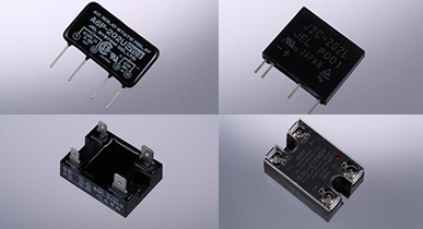
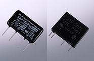
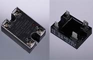
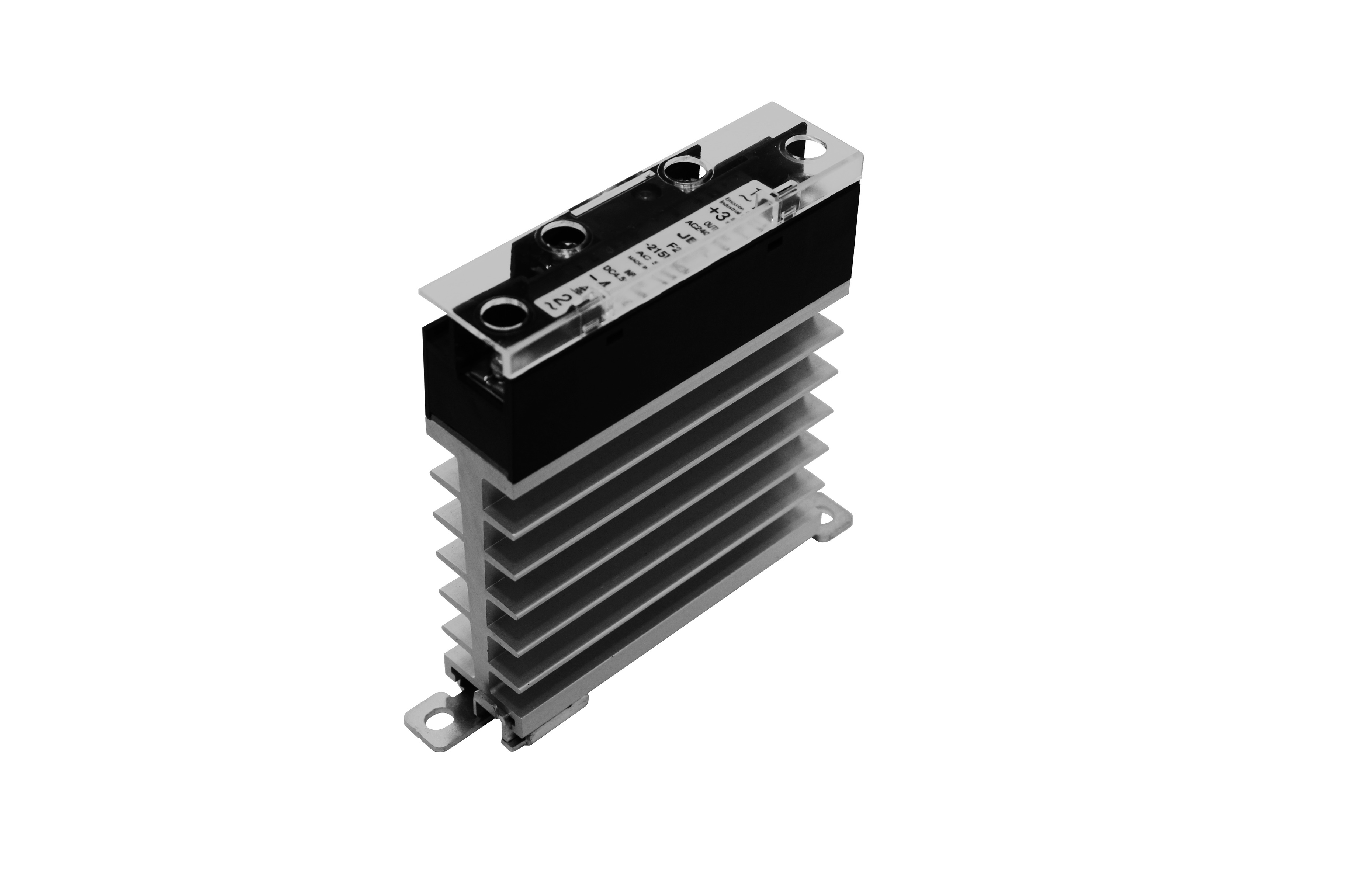
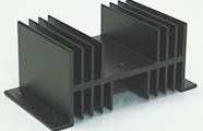
Solid State Relays
This is a non-contact semiconductor control component that uses semiconductor devices for switching electric circuits ON/OFF.
Outline
A solid state relay (SSR) is a non-contact semiconductor control component where the input side and output side are isolated like an electromagnetic relay (EMR), and a function which matches the ON/OFF of the input and output is provided for switching electric circuits ON/OFF using semiconductor devices.
Application Range
SSRs are not only used in industrial machinery, such as machining centers and industrial robots, but are also widely used in the following fields which support electric appliances and our daily lives.
Examples:
- Office equipment, such as copy machines, phototypesetting machines, facsimile, telephone switchboards, and computer terminals
- Equipment, such as NC machine tools, elevators, industrial robots, electric lighting, sequencers (PLCs), and temperature controllers
- Electric appliances, such as microwave ovens, power tools, sewing machines, air conditioners, washing machines, and refrigerators
- Lighting equipment, such as signals, lighting display boards and dimmers
- Vending machines, automatic vending machines, automatic ticket gates, ticket machines, money changers
- Amusement equipment, such as UFO catchers and racing games
- Semiconductor manufacturing equipment, such as steppers, bonding machines, and diffusion furnaces
- Other various electrical equipment
Features
- ・Using a optocoupler (photocoupler) in the circuit realized high reliability, high speed, high frequency control and miniaturization compared with an electromagnetic relay (EMR).
- ・The SSR operates on a low signal, and has excellent vibration resistance, impact resistance and moisture resistance.
- ・The SSR also has excellent environmental characteristics without noise.
Specifications
1. Operating Principle
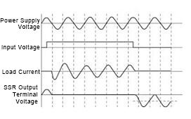
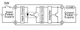
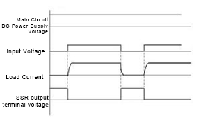
1) Operating principle of SSR for AC loads (Zero-cross built-in type)
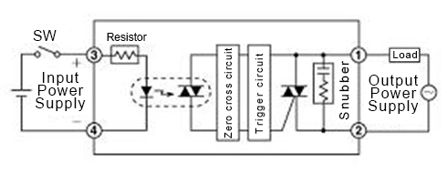
When the switch is turned ON, the current flows into the light emitting diode and the optically coupled photocoupler turns ON. The zero-crossing circuit operates and turns ON the triac of the output circuit close to the zero voltage of the AC power voltage. Accordingly, the current flows to the load from the power supply via the triac. When the switch is turned OFF, the solid state relay (SSR) turns OFF close to the zero of the load current due to the operating characteristics of the triac. The current waveform flowing into this load changes by the type of load.
Resistive Loads
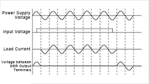
When an input voltage is applied near the peak value of the AC power voltage, the current will not flow immediately to the SSR output circuit. When the voltage becomes close to zero due to a drop in the AC power voltage, the triac of the SSR output circuit turns ON, and the current will flow to the load. During this process, the AC power voltage and the load current remain the same phase. Even when the input voltage is turned OFF, the SSR does not turn OFF immediately. It turns OFF when the load current decreases and reaches below the holding current of the triac.
Inductive Loads
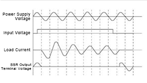
When an input voltage is applied near the peak value of the AC power voltage, the current will not flow immediately to the SSR output circuit. When the voltage becomes close to zero due to a drop in the AC power voltage, the triac of the SSR output circuit turns ON, and the current will flow to the load.
In this case, since the load is inductive, the current peak value of the first cycle becomes high due to the transient phenomenon, and the current peak value becomes low and reaches a steady state along with the successive progression of the cycle.
The phase of the load current during this process is delayed up to 90 degrees to the phase of the AC power voltage.
Even when the input voltage is turned OFF, the SSR does not turn OFF immediately. It turns OFF when the load current decreases and reaches below the holding current of the triac.
Capacitive Loads
When an input voltage is applied near the peak value of the AC power voltage, the current will not flow immediately to the SSR output circuit. When the voltage becomes close to zero due to a drop in the AC power voltage, the triac of the SSR output circuit turns ON, and the current will flow to the load.
The phase of the load current during this process advances up to 90 degrees to the phase of the AC power voltage.
Even when the input voltage is turned OFF, the SSR does not turn OFF immediately. It turns OFF when the load current decreases and reaches below the holding current of the triac.
Note that since this is a capacitive load, the voltage generated by an electric charge stored in the capacitor and the power supply voltage will be added, and a voltage double the peak value of the power supply voltage may be applied to the SSR. Therefore, when using an SSR with a power supply voltage of 110V, SSR for 220V is recommended to be used.
2) For DC Loads
Transistor Output
The input and output are isolated by the photocoupler. The output side consists of a waveform shaping circuit, amplifier, and output device (transistor). When the switch is turned ON, current flows into the LED of the photocoupler and the optically coupled phototransistor turns ON, and drives the output device (transistor) via the shaping circuit and amplifier. Accordingly, the transistor turns ON, and the load current flows.
When the switch is turned OFF, the phototransistor turns OFF, the transistor turns OFF and the load current shuts down.
FET Output
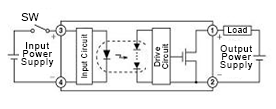
The input and output are isolated by the photocoupler. The output side consists of a drive circuit and output device (MOSFET). When the switch is turned ON the current flows into the LED of the photocoupler, and an electromotive force occurs in the optically coupled photodiode array, which drives the gate of the output device (MOSFET). Accordingly, the MOSFET turns ON, and the load current flows. When the switch is turned OFF, the electromotive force of the photodiode array turns OFF, and the electric charge which accumulated in the gate of the MOSFET discharges via the drive circuit which turns OFF the MOSFET and shuts off the load current.
Resistive Loads
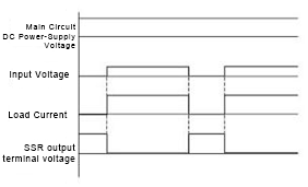
When an input voltage is applied, the current immediately flows to the load.
When the input voltage is turned OFF, the load current immediately becomes zero.
Inductive Loads
When an input voltage is applied, the current starts flowing to the load.
In this case, since this is an inductive load a time delay occurs until the load current becomes a steady state.
When the input voltage is turned OFF, the load current gradually decreases to zero.
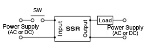
2. Application Circuits
1) Example of Solid State Relay (SSR) Drive Circuit
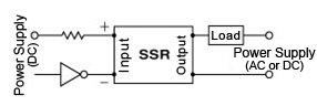
When operated by a limit switch
When the contacts are ON, the SSR remains ON.
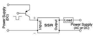
When operated by a NPN transistor
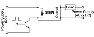
When the transistor is ON, the SSR remains ON.
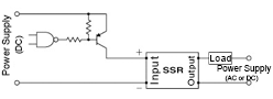
When operated by a NPN transistor
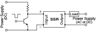
When the transistor is OFF, the SSR remains ON.
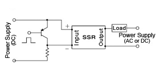
When operated by a PNP transistor
When the transistor is ON, the SSR remains ON.
When operated by a PNP transistor
When the transistor is OFF, the SSR remains ON.
AC Drive
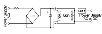
When driving a SSR for DC input with an AC power supply, it can be used by externally mounting a rectifier circuit.
(Confirm that the ripple is within the operating voltage range of the SSR.)
When operated by a TTL or DTL
When the IC output is at the L level, the SSR remains ON.
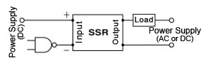
When operated by a CMOS IC
When the IC output is at the L level, the SSR remains ON.
When operated by a C-MOS IC
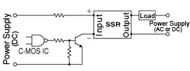
When the IC output is at the H level, the SSR remains ON.
When operated by a C-MOS IC
When the IC output is at the L level, the SSR remains ON.
2) Examples of Controlling Various Loads
Flickering control of incandescent lamps
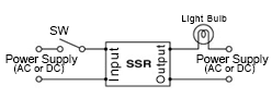
Since a large inrush current flows when an incandescent lamp is turned ON (about 10 times the steady state), please use within the range of each surge current characteristic.
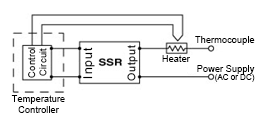
Temperature Control of Electric Furnace
Solenoid Valve Drive
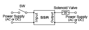
In the case of a solenoid load, an inrush current flows at the initial stage of operation, and constant current flows after several cycles.
Please use within the range of each surge current characteristic.
Miniature Relay Drive Circuit
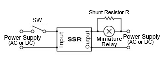
There are miniature relays where the operating current is low and operate at several mA. Therefore, the leakage current flows when the SSR is OFF, and miniature relays may operate with this current. To avoid this, it is necessary to connect a shunt resistor R in parallel with the load to shunt the leakage current when the SSR is OFF.
Neon Lamp Flashing Control
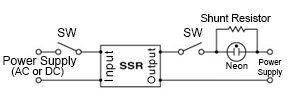
Connect a shunt resistor R in parallel with the neon lamp so that glow discharge of the neon lamp does not occur by leakage current when the SSR is OFF.
ON/OFF Control of Single-Phase Inductive Motor
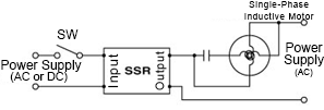
An inrush current flows at the initial operation of a motor. Please use within the range of each surge current characteristic.
CW/CCW Operation of Single-Phase Inductive Motor
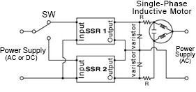
The voltage between the load terminals of the SSR on the side where either SSR1 or SSR2 is turned OFF becomes double the voltage of the power supply voltage depending on the characteristics of the LC circuit of the motor. Therefore, be sure to use a SSR with double the rated voltage of the operating power supply. Provide a time lag for the changing the switch. (At least 30ms is required)
How to Select Protective Resistance R
The protective resistance R protects the SSR from damage due to overcurrent. The resistance value is calculated from the maximum surge current rating (non-repetitive) of the power supply voltage and the SSR.
R > √2 x power supply voltage ÷ maximum surge current rating (non-repetitive)
The power resistance P can be calculated from the load current and protective resistance R values.
P > (load current)2 x R
When making a selection, it is recommended that a protective resistance R with double or more than the calculated value be selected in consideration of a margin.
ON/OFF Control of Three-Phase Inductive Motor
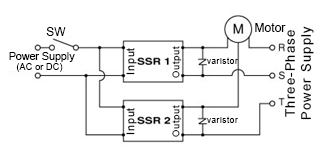
An inrush current flows at the initial operation of a motor. Please carefully select the SSR. Two SSRs are connected to two of the three-phase 3 wires.
This circuit is always connected to a motor and power supply therefore, please be careful of deterioration of the insulation of the motor and electric shocks caused by the motor being electrically charged.
To ensure safety, connect a no-fuse breaker before the SSR, and it is preferable to turn OFF the power when not being used.
ON/OFF Control of Three-Phase Heater
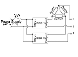
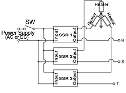
Use the SSR so that sufficient voltage within the input voltage range is applied to the input side.
When grounding the neutral point of a three-phase star connection to use the SSR, it may fail due to excessive voltage being applied to the SSR if the neutral point is disconnected. Be sure to connect the ground securely.